Sized for the Stop, Not the Catalogue: A Duty-Cycle Method for Bosch Brake Resistors
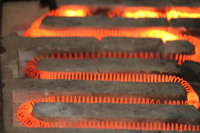
Brake resistors are among the most frequently reused components in a UK drive retrofit. The old resistor is already mounted, already wired and apparently already rated, so it is tempting to leave it in place while the drive and motor are updated. That approach can work, but only when the resistor has been assessed against the new stopping duty rather than the old catalogue line. A resistor does not absorb continuous power in the way a motor does. It absorbs energy in pulses, stores heat in a ceramic or wire element, and releases that heat through an enclosure that may be considerably warmer than the plant room.
Begin with the deceleration, not the resistor
The first number to establish is the energy that must be removed during the worst credible stop. For a rotating load, the kinetic energy available at the start of braking is:
E = 0.5 × J × (ω1² − ω2²)
where J is the total inertia reflected to the motor shaft and ω is angular velocity. For a horizontal conveyor this may be the dominant term. For a hoist or an inclined conveyor, potential energy must be added. Friction and load losses reduce the energy that reaches the DC bus, but they should not be assumed to be generous. In a retrofit, the safest starting point is the measured or documented inertia, the maximum line speed and the stopping time required by the risk assessment.
Consider a 7.5 kW conveyor motor running at 1450 rpm with a reflected inertia of 0.35 kg·m². At 151.8 rad/s, the stored energy is approximately 4.0 kJ. If the drive brakes the load to standstill in 1.5 seconds, the average braking power during that pulse is about 2.7 kW. If the conveyor stops every 30 seconds, the long-term average is only about 134 W. Both figures matter, but they describe different limits. The 2.7 kW figure stresses the resistor element and its internal connections; the 134 W figure determines the average heat that the enclosure must dissipate.
Turn the profile into a resistor duty cycle
A single stop is rarely the whole story. UK packaging lines, sortation conveyors and fan systems often have repeatable cycles with several decelerations per minute, followed by long idle periods. The resistor must survive the worst short window, not just the shift average. Build a simple duty table listing the braking time, the repetition period and the energy per stop for the busiest ten-minute period. Include emergency stops separately, because an emergency stop may combine a higher initial speed with a shorter deceleration time and a different drive parameter set.
Where the resistor manufacturer provides pulse diagrams, use them. These graphs show how a resistor may be overloaded for short periods provided the average remains within the thermal limit. Where no such data is available, adopt a conservative rule: the continuous rating should exceed the calculated average with margin, and the pulse power should remain within the manufacturer's short-time rating for the stated braking time. Do not select by continuous watts alone. A resistor that looks adequate on average can still fail after repeated short stops because the element has not had time to release heat.
The enclosure is part of the thermal circuit
A brake resistor mounted inside a control cabinet is not in free air. Its heat raises the internal temperature, and the cabinet must reject that heat through its surface, fans or filter. The ambient used for resistor derating should be the temperature inside the enclosure during the hottest expected production period, not the shaded air temperature on the plant floor. In UK plants, cabinet roofs near ovens, dryers or steam lines can run well above the room figure, and a resistor that is adequate in January may be marginal in a July shutdown period.
Check the manufacturer's ambient rating and apply the derating curve. Confirm the mounting orientation, clearance to adjacent components and the temperature rating of nearby cables. A resistor with a surface temperature above 200 °C will not be kind to PVC insulation or plastic trunking. Fit the thermal switch or thermostat provided with the resistor and wire it to inhibit the drive; a warning label alone is not a protection scheme. Fuse coordination should also be checked, because a resistor fault is a fire risk as well as an electrical one.
Voltage tolerance changes the pulse power
The drive switches the resistor across the DC bus at a defined threshold. That threshold is not a fixed constant. UK supplies are nominally 400 V, but the permitted tolerance means the rectified bus can be higher than the nominal calculation suggests. A higher mains voltage gives the resistor more voltage across it and therefore more pulse power for the same resistance. Resistor tolerance works in the opposite direction: a lower resistance increases current and power.
Check the drive parameter for the braking threshold and confirm that the resistor voltage rating is suitable. Do not raise the threshold casually to reduce braking energy; it may reduce resistor duty but increase bus stress elsewhere. Do not lower it without checking that the resistor can absorb the resulting energy and that the drive's braking unit is rated for the current. The correct setting is the one supported by the drive manual and the thermal calculation, not the one that makes a nuisance trip disappear.
Prove the installation before the emergency stop
An emergency stop should not be the first full-energy braking event. Commission in stages. Run the drive at low speed with a light load and confirm that the DC bus rises and falls as expected. Use the drive's trace or a suitable meter to observe braking current and duration. Repeat the stop at increasing speed and inertia while monitoring resistor temperature and cabinet temperature. Check the thermal switch trip point by safe simulation where the hardware allows it, and verify that the drive inhibits as intended.
After several representative cycles, inspect the resistor and its terminations with a thermal camera. Look for hot spots at crimps, discoloured insulation and uneven element temperature. Record the duty cycle, the drive threshold and the measured temperature rise in the commissioning file. That record is the evidence that the resistor was selected for the actual stop, not inherited from a previous drive. When the line changes speed, load or stopping frequency, revisit the calculation. The resistor is sized for the duty cycle, and the duty cycle belongs to the process.