Distance and Damage: Assessing Reflected-Wave Risk on Remote Bosch Motor Installations
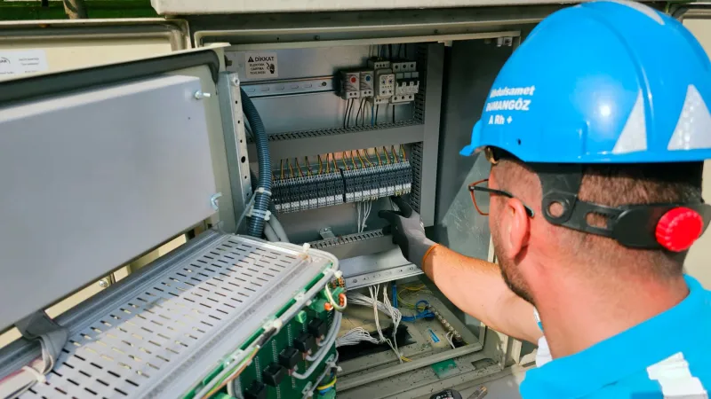
Retrofits rarely respect the tidy assumptions of a drive datasheet. The panel goes where there is space and a clean supply; the motor stays where the process needs it. On a UK site that can easily mean 60, 80 or 100 metres of cable between the two, routed through a riser, across a roof deck and down into a pump house. The drive will still run the motor. The question is how long the motor insulation will tolerate the way it is being run.
What the cable does to the waveform
A PWM output stage does not deliver a sine wave. It delivers a train of fast-edged pulses, and those edges travel down the cable as a travelling wave. At the motor terminals the surge impedance rises sharply, so the wave reflects back towards the drive and superimposes on the pulse still arriving. When the cable is long enough that the round-trip transit time exceeds the pulse rise time, the result is a terminal voltage approaching twice the DC bus voltage.
On a 400 V system the DC bus sits somewhere around 565 V at nominal and can reach 650 V or more at the top of the supply tolerance. Doubling that puts peak terminal voltage in the region of 1,200 to 1,350 V. A motor qualified to Type I insulation limits under IEC 60034-18-41 — broadly 1,000 V plus twice the rated voltage, so 1,800 V for a 400 V machine — will absorb that. A motor with an unknown history, a rewind of uncertain provenance, or a winding that has already spent fifteen years at elevated temperature may not.
The risk is not a single pulse. It is the repetition. Fast edges stress the first turns of each phase winding, and repeated partial discharge at those turns erodes enamel from the inside. The failure mode appears as an earth fault or a phase-to-phase short months later, far from the installation work that caused it, which is why the assessment belongs in the retrofit survey rather than in the post-mortem.
The variables that actually decide the outcome
Five factors govern whether a given installation is comfortable or marginal.
- Cable length, as routed. Not the distance on the layout drawing. Add the vertical drops, the spare loop left in the tray, and the extra few metres around the cable gland.
- Cable capacitance per metre. Screened motor cable typically runs 100–200 pF per metre, with armoured and foil-screened constructions at the upper end. Capacitance raises the drive's output current and the common-mode current in the screen, and it lowers the length at which reflections become significant.
- Drive output rise time. Modern output stages switch in 50–200 ns. Shorter edges mean reflections matter over longer cable runs; a drive with a genuinely slow edge is more forgiving.
- Switching frequency. Raising it from 4 kHz to 8 kHz or 16 kHz to quieten the motor acoustically doubles or quadruples the number of stress cycles per second at the winding, and increases filter and cable losses. Default settings are usually sufficient; be sceptical of raising them by habit.
- Screen bonding. A screen earthed at one end only is an aerial, not a shield. Bond both ends, 360° at the gland, using the correct EMC gland and a bare metal contact to the enclosure. This is a BS 7671 earthing and bonding matter as much as an EMC one.
A staged assessment for retrofit work
1. Establish the as-built distance
Walk the route with a measuring wheel or use the cable schedule, and record the figure. Confirm whether the installed cable is the screened motor cable specified or something that was to hand — SY, CY, armoured multicore and singles in steel conduit all behave differently.
2. Characterise the cable
Note conductor size, capacitance per metre from the manufacturer's data, screen construction, and whether parallel cables are used per phase. Parallel runs increase capacitance and require symmetrical routing; a single cable left overlong in one phase creates an imbalance that shows up as circulating current in the screen.
3. Read the drive's output data
Confirm the DC bus voltage at the actual supply level, the factory output rise time, and the switching frequency as configured. Check whether the drive already has an output reactor or filter fitted and, if so, whether it is correctly rated for the cable length and the motor current.
4. Check the motor's insulation qualification
Ask for the motor datasheet and look for the converter-duty designation under IEC 60034-25 and the insulation qualification under IEC 60034-18-41. A Type II machine is qualified for higher pulse stress and is the right choice for long cable runs. If the motor is older, rewound, or the documentation is missing, treat it as Type I and assess conservatively. Insulation class F or H describes thermal capability, not pulse withstand — the two are often conflated in site conversations.
5. Decide on mitigation, and record the decision
Where the calculated peak voltage at the motor terminals sits comfortably within the motor's qualification, with a sensible margin for supply tolerance, no filter is needed. Where it does not, choose deliberately:
- Output reactor — a modest, inexpensive measure that slows the edge and reduces peak voltage; useful at moderate lengths and for reducing common-mode current.
- dv/dt filter — clamps the rate of rise and limits peak terminal voltage, and is the usual answer for long runs on 400 V systems.
- Sine filter — produces a near-sinusoidal output and permits very long cables, at the cost of weight, space, heat and a small voltage drop that must be allowed for in the motor selection.
- Relocation — sometimes the cheapest filter is a shorter cable.
What to leave behind at handover
The value of this work lies in the record as much as the hardware. Log the as-built cable length and type, the drive's switching frequency and output filter configuration, the motor's insulation qualification with the datasheet reference, and the calculated or measured peak voltage at the motor terminals. A portable oscilloscope with a suitable high-voltage differential probe, used during commissioning, converts the calculation into evidence.
Then run the machine under load for a few hours and thermographically check the motor terminal box and the first metre of cable. Warmth there is not a fault in itself, but it is a baseline, and baselines are what make the next inspection useful. Long cable runs are not a defect in a retrofit. Unconsidered ones are.