Beyond Type AC: Getting Earth-Leakage Protection Right on Bosch Drive Retrofits
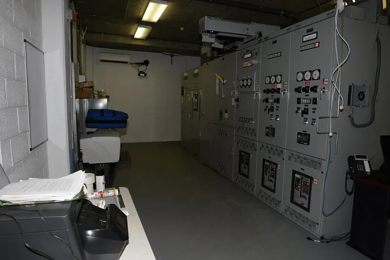
Photo: Federal Bureau of Investigation, Public domain, via Wikimedia Commons
A residual current device that has protected a motor control centre for twenty years does not automatically remain the right device once a variable speed drive is added to it. The RCD itself has not changed, but the current it is being asked to interpret has: a diode bridge, a switched output stage and several hundred metres of screened motor cable present a residual current signature that the original designers of Type AC devices never anticipated.
None of this makes a Bosch drive unsafe, and none of it justifies a reflex decision to fit a 30 mA device on every feed. It does, however, mean that the selection of earth-leakage protection deserves the same engineering attention as cable sizing or fault level.
What the drive places on the protective conductor
Three distinct components of residual current arise in a drive-fed circuit, and they behave very differently.
The first is power-frequency capacitive leakage. Every EMC filter, every screened motor cable and every long run of parallel conductor contributes a small 50 Hz current to earth. In a panel with several drives and generous cable lengths, this can accumulate to tens of milliamps, all of it entirely normal.
The second is high-frequency leakage from the PWM output stage, which couples through the filter capacitors and the cable screen. It is largely invisible to standard measurement and even less visible to a conventional RCD tester.
The third appears only under a fault condition: a smooth, direct residual current from the input rectifier. It is this component that dictates device selection, because a smooth DC residual of only a few milliamps can saturate the sensing toroid of a Type A device and desensitise it to the alternating fault current it is there to detect.
Sorting the device types
- Type AC detects alternating residual current only. BS 7671 increasingly constrains its use, and it should not be installed where equipment capable of producing a DC residual component is present.
- Type A detects alternating and pulsating direct residual current. It is the common default in UK distribution boards and is entirely appropriate where no smooth DC component can arise.
- Type B detects alternating, pulsating and smooth direct residual current, and is the device that covers the rectifier front end of a drive.
- Type B+ is a Type B device with enhanced immunity to high-frequency leakage and a higher surge withstand. Where a plant has suffered repeated nuisance trips on a correctly selected Type B, a B+ device is often the engineering answer rather than a larger rating.
What the regulations and the manual together require
BS 7671:2018+A2:2022, at Regulation 531.3.3, requires the type of RCD to be selected with regard to the nature of the residual current the circuit may produce, and specifically warns against Type AC where DC components are likely. Regulation 134.1.1 requires equipment to be installed in accordance with the manufacturer's instructions, which makes the Bosch drive documentation a design input rather than a reference document.
What the regulations do not require is an RCD on every drive circuit. Where automatic disconnection of supply is achieved by an overcurrent protective device and the earth fault loop impedance is verified as adequate, a compliant installation may have no RCD on the drive feeder at all. Introducing one where none is needed simply creates a nuisance-trip liability and an additional item to maintain. The decision should be recorded either way.
The retrofit problem in practice
The difficult cases are rarely new panels. They are 1990s motor control centres on a TN-S supply, with a 300 mA Type AC device at the intake and a proposal to add three Bosch drives and a submain to a new bay. The questions that follow are predictable: does the existing intake device remain acceptable, does the new submain require its own protection, and what happens to the 30 mA socket-outlet circuit in the corner of the room?
The productive approach is a short survey before any device is ordered. Record the type marking and rated residual operating current of every RCD in the distribution path. Identify any existing load capable of producing a DC residual component — an EV charge point, a photovoltaic inverter, an ageing drive from another manufacturer — because those loads already affect the upstream device. Then read the Bosch documentation for each new drive, paying particular attention to the stated earth leakage current with filters fitted, the permissible filter configuration for the earthing system in use, and any explicit statement about upstream RCD type.
Where the drive documentation states that a fixed protective conductor connection is required because leakage exceeds 3.5 mA AC, that is a permanent connection requirement, not a recommendation. Note also that the quoted figure is a power-frequency value; the high-frequency content that causes most nuisance tripping is not represented in it.
Commissioning checks that will hold up
Before energising, confirm the type marking and manufacturer of each device against the panel schedule, carry out insulation resistance testing with the drives disconnected, and verify protective conductor continuity and sizing.
On energisation, measure the standing leakage on each feeder with a true-RMS leakage clamp capable of responding to the harmonic content. Log the value per drive and compare it with the figure anticipated at design stage. A measured value materially above expectation usually indicates a screen bonding fault, a filter configuration mismatch or an unexpectedly long motor cable.
RCD testing requires an instrument rated for the device type. A Type B device cannot be verified with a tester that only produces alternating and pulsating test currents; the results will be misleading in both directions. Test at half the rated residual operating current to confirm no trip, at rated current to confirm operation within the tabulated time, and at five times rated current. Record the instrument, the values and the date.
Keeping the protection valid over time
The protection is only as good as the last verification. A twelve-monthly instrumented test, with the push-button functional check in the intervening period, forms a defensible routine, and the schedule should be brought forward whenever drives are added, filters are reconfigured or a circuit is re-fed. Any panel modification should trigger a review of the RCD type, not merely of the rating.
Finally, update the panel schedule and the EICR information to state the RCD type and the reason for its selection. The recurring argument over whether a Type B is really necessary is settled far more quickly by a dated record of the drive documentation, the leakage measurement and the test results than by precedent.