Cool Frame, Hot Trip: Verifying Overtemperature Alarms on Bosch Motors
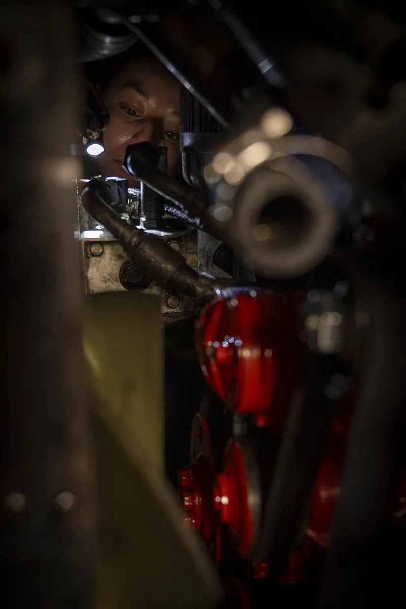
Photo: U.S. Navy photo by Petty Officer 2nd Class Caylen McCutcheon, Public domain, via Wikimedia Commons
A Bosch motor reports an overtemperature condition, yet the frame is cool to the touch. The immediate temptation is to treat the trip as nuisance protection and look for a way around it. That is the wrong starting point. The drive is reporting a measurement, not delivering a verdict. Until the signal path, sensor type and configuration have been checked, neither a rewind nor a replacement is an evidence-based decision.
On UK sites, false overtemperature trips often appear after a motor retrofit, a drive replacement or a period of maintenance inactivity. The motor may be sound, the sensor may be serviceable and the drive may be correctly installed, but one detail in the chain has changed. The following route is intended to help plant teams establish where the trip originates before committing to major works.
The Trip Is a Measurement, Not a Verdict
Bosch drive systems may derive an overtemperature trip from an embedded winding sensor, from a drive thermal model, or from a combination of both. The first step is therefore to establish what the drive was actually evaluating at the moment of the trip. Capture the fault code, the time stamp, the load condition, the ambient temperature and the active motor parameters. If the drive keeps a fault history, export it before clearing anything.
A cool frame does not prove that the winding is cool. Embedded sensors are intended to sit close to the winding hot spot, which can be significantly warmer than the external frame, particularly during short overloads or when the motor is mounted in a restricted enclosure. Equally, a hot trip does not prove that the sensor is faulty. Both possibilities must remain open until the evidence narrows the field.
Identify the Feedback Type Before Testing
The three common winding-temperature feedback types behave differently and are not interchangeable at the drive terminals. A PTC thermistor is non-linear: its resistance remains relatively low until the nominal response temperature is approached, then rises sharply. A KTY sensor is broadly linear and is often used by drives to provide a continuous temperature indication. A PT100 is a platinum resistance sensor with a well-defined resistance-temperature relationship and is normally used with two-, three- or four-wire connection arrangements.
Before measuring anything, confirm the sensor type from the motor documentation, the terminal-box marking and the drive parameter set. A mismatch here is one of the most common causes of false trips after a retrofit. A drive configured for a KTY sensor will not interpret a PT100 correctly, and a PTC input will not behave as expected if it is presented with a linear resistance. The result can be a trip at a plausible but incorrect temperature.
Lead Resistance and Screening Effects
Sensor wiring is part of the measurement circuit. On a two-wire PT100, lead resistance adds directly to the measured value. Because a PT100 changes by approximately 0.385 ohms per degree Celsius, a one-ohm loop error can represent around 2.6 degrees Celsius of apparent temperature error. Three- and four-wire arrangements reduce or eliminate this effect, but only if the correct cable and drive input configuration are used.
PTC circuits are less sensitive to small changes in lead resistance, but they are not immune to wiring problems. Loose terminals, corrosion, moisture ingress and contaminated terminal boxes can all produce intermittent or misleading readings. Screening also matters. Sensor cables routed alongside motor power cables may pick up noise, particularly on long runs or on installations with high switching frequencies. The screen should be terminated in accordance with the drive manufacturer's EMC guidance, normally at the drive end, and the cable should not be used as a convenient parallel path for other signals.
Insulation testing of sensor wiring requires care. High-voltage insulation tests should not be applied to sensor circuits unless the sensor and drive input are isolated and the test is permitted by the relevant documentation. A better first check is a low-voltage continuity and resistance measurement at the motor terminal box, taken with the motor safely isolated and the sensor wiring disconnected from the drive where necessary.
Parameter Mismatch After Retrofit
Retrofits introduce a predictable set of configuration risks. A replacement motor may be fitted with a PT100 sensor while the drive remains configured for the original KTY device. A new drive may be commissioned with default thermal parameters that do not match the motor. A PTC response threshold may be set for a different insulation class or application. Filtering may be too fast, causing transient trips during acceleration, or too slow, masking a genuine rise.
These are not obscure faults. They are ordinary commissioning details that become significant when the motor and drive are no longer a matched pair. The remedy is documentary as well as technical: compare the motor nameplate, sensor marking, drive parameter list and commissioning record. Where a retrofit has changed the sensor type, the drive input configuration and alarm thresholds should be updated deliberately and recorded.
A Verification Sequence for UK Plant Teams
A structured sequence is more reliable than replacing parts in the hope that the trip disappears.
- Capture the event. Record the fault code, operating condition, ambient temperature, motor current and drive parameters before clearing the fault.
- Confirm the sensor type. Check the motor documentation and terminal box against the drive configuration.
- Measure at the motor. With the motor isolated, measure sensor resistance at the terminal box and compare it with the expected value at the prevailing ambient temperature.
- Inspect the wiring. Check continuity, terminal tightness, screen termination and signs of moisture or corrosion. Confirm that sensor cables are separated from power cables as far as practicable.
- Test the drive channel. Using a calibrated resistance source or decade box, simulate the sensor at ambient and at the trip threshold at the drive terminals. Confirm that the drive responds at the expected value. This separates a sensor or wiring fault from a drive input or parameter fault.
- Run a controlled load check. If the signal path is correct, run the motor under a known load and compare the drive reading with an independent reference, such as a thermal camera or a calibrated contact thermometer at accessible points. A cool frame with a rising winding indication points towards a genuine internal thermal problem; a stable winding indication with a spurious trip points back towards the signal path.
When the Winding Is Actually Hot
Not every overtemperature trip is false. If the measured winding resistance rises with load and falls after the motor is stopped, the drive may be reporting a genuine thermal condition. In that case, the investigation should move to cooling, duty cycle, enclosure ventilation, voltage imbalance, harmonic distortion and mechanical overload. Rewinding or replacement should follow from that evidence, not from the alarm alone.
Disabling overtemperature protection is not a repair. It removes the evidence and leaves the motor exposed to thermal damage that may not be visible until insulation failure occurs. A false trip is usually cheaper to correct at the sensor, wiring or parameter level than a rewind, and a genuine trip is cheaper to investigate than a burnout.
For Bosch Motors & Controls UK readers, the practical message is straightforward: treat the trip as a measurement, verify the sensor type and signal path, and only then decide whether the motor has a thermal problem. The frame temperature is useful context, but it is not the measurement that matters.